Arduino_store
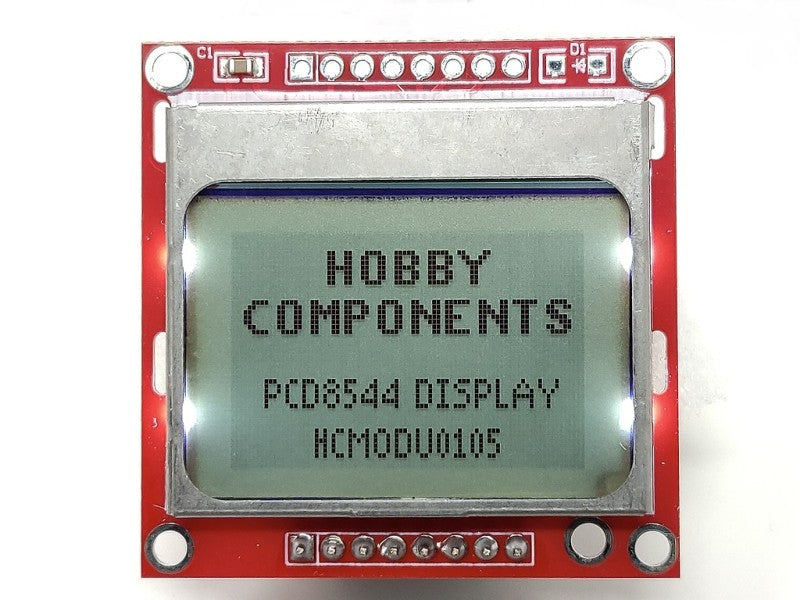
Red Nokia 5110 84x48
Red Nokia 5110 84x48
Couldn't load pickup availability
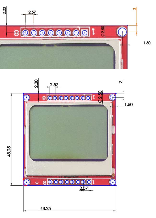
Pin Configuration :
(Reset) RST—-> D3
(Chip Selection) CE—->D4
(Data/Commands Choice) DC—->D5
(Serial Data Line)Din—->D6
(Serial Clock Speed.)CLK—->D7
(Backlight Control Terminal) BL—->Gnd
Vcc—-> 5v to 7V
Gnd—>Gnd
Pin No:Pin Name:Description1ResetThis pin resets the module. It an active low pin (resets when 0V is provided)2Chip Enable (CE)This pin is made low (0V) to select this particular display when more than one SPI peripherals are used.3Data/Command (DC)This pin is used to switch between Data mode (high) and Command mode (low)4Serial Input (DIN)This is the input pin (MOSI) through which serial instructions are sent5Clock (CLK)All SPI modules require a common clock, this clock source is supplied to this pin6Power (Vcc)This pin is used to power the display the supply voltage is from 5V to 7V7Back Light (BL)Connects to the ground of the circuit.8Ground (Gnd)Connects to the ground of the circuit.
Share